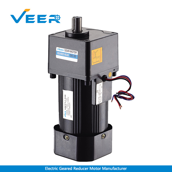
Description
Technical Parameter Sheet of Geared Motor
| Motor Model | Power (W) | Voltage (V) | Frequency (Hz) | Current (A) | Starting Torque (mN.m) | Rated Torque (mN.m) | Rated Speed (r/min) | Rated Time (min) | Capacitance (μF/VAC) | ||
|---|---|---|---|---|---|---|---|---|---|---|---|
| Veer’s Model | Standard Model | ||||||||||
| Induction Motor
Variable Speed Motor Brake Motor |
100YYJT250-1 | 6IK250(R)GN-A | 250 | 1-phase/110 | 50 | 3.5 | 1200 | 1790 | 1300 | Continuous | 48/250 |
| 60 | 3.2 | 996 | 1485 | 1500 | |||||||
| 100YYJT250-3 | 6IK250(R)GN-C | 1-phase/220 | 50 | 1.80 | 1200 | 1790 | 1300 | 10/450 | |||
| 60 | 1.66 | 996 | 1485 | 1500 | |||||||
| 100YSCJ250-3 | 6IK250GN-S | 3-phase/220 | 50 | 1.60 | 3600 | 1790 | 1300 | ||||
| 60 | 1.48 | 2988 | 1485 | 1500 | |||||||
| 100YSCJ250-4 | 6IK250GN-U | 3-phase/380 | 50 | 1.05 | 3600 | 1790 | 1300 | ||||
| 60 | 0.97 | 2988 | 1485 | 1500 | |||||||
Notes:
1) The parameters in the above sheet refer to only geared motor itself, without any load attached.
2) The permissible variation range of the rated rotate speed, and rated current of the motor is within ±%5.
Allowable Torque Sheet of Geared Motor
| Reduction Ratio | 3 | 3.6 | 5 | 6 | 7.5 | 9 | 10 | 12.5 | 15 | 18 | 20 | 25 | 30 | 36 | 40 | 50 | 60 | 75 | 90 | 100 | 120 | 150 | 180 | 200 | 250 | 300 | |
|---|---|---|---|---|---|---|---|---|---|---|---|---|---|---|---|---|---|---|---|---|---|---|---|---|---|---|---|
| 50Hz | REV. (r/min) | 500 | 417 | 300 | 250 | 200 | 166 | 150 | 120 | 100 | 83 | 75 | 60 | 50 | 41 | 37 | 30 | 25 | 20 | 16 | 15 | 12.5 | 10 | 8.3 | 7.5 | 6 | 5 |
| Torque (N.m) | 3.01 | 3.61 | 5.01 | 6.02 | 7.52 | 9.03 | 10.0 | 12.5 | 15 | 18 | 20 | 25.1 | 30.1 | 36 | 40.1 | 44 | |||||||||||
| Torque (kgf.cm) | 30.1 | 36.1 | 50.1 | 60.2 | 75.2 | 90.3 | 100 | 125 | 150 | 180 | 200 | 251 | 301 | 360 | 401 | 440 | |||||||||||
| 60Hz | REV. (r/min) | 600 | 500 | 360 | 300 | 240 | 200 | 180 | 144 | 120 | 100 | 90 | 72 | 60 | 50 | 45 | 36 | 30 | 24 | 20 | 18 | 15 | 12 | 10 | 9 | 7.2 | 6 |
| Torque (N.m) | 2.5 | 3.01 | 4.18 | 5.01 | 6.27 | 7.52 | 8.36 | 10.4 | 12.5 | 15 | 16.7 | 20.9 | 25 | 30.1 | 33.4 | 41.8 | 44 | ||||||||||
| Torque (kgf.cm) | 25 | 30.1 | 41.8 | 50.1 | 62.7 | 75.2 | 83.6 | 104 | 125 | 150 | 167 | 209 | 250 | 301 | 334 | 418 | 440 | ||||||||||
Notes:
1) The rotate speed is calculated from synchronous speed of the motor dividing reduction ratio. Actual rotate speed will decrease about 2-20% from theoretical rotate speed along with load changes.
2) If you want the reduction ratio is greater than the sheet above, please install a new reducer between motor and existing reducer, which reduction ratio is about 10.
Optional Models of 250W Geared Motor
| ① Circular Shaft Model | |
|---|---|
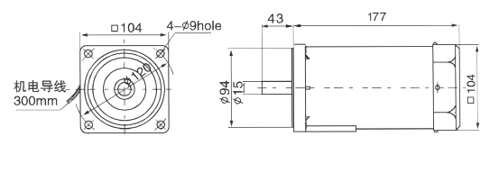 |
|
| Structure: Motor | |
| ② Constant Speed Model (Shaft: φ15) | ③ Junction Box Model (Shaft: φ15) |
 |
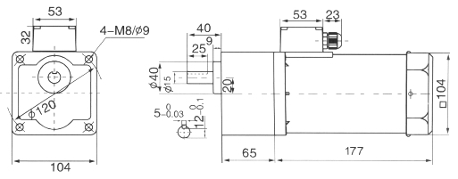 |
| Structure: Reducer+Motor | Structure: Reducer+Motor+Junction Box |
| ④ Constant Speed Model (Shaft: φ18) | ⑤ Junction Box Model (Shaft: φ18) |
 |
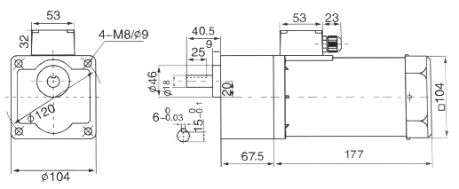 |
| Structure: Reducer+Motor | Structure: Reducer+Motor+Junction Box |
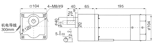
| ⑥ Constant Speed with Brake Model (Shaft: φ15) | ⑦ Variable Speed with Brake Model (Shaft: φ15) |
 |
 |
| Structure: Reducer+Motor+Brake | Structure: Reducer+Motor+Brake+Speed Controller (Additional) |
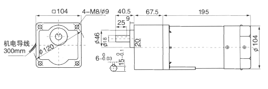
| ⑧ Constant Speed with Brake Model (Shaft: φ18) | ⑨ Variable Speed with Brake Model (Shaft: φ18) |
 |
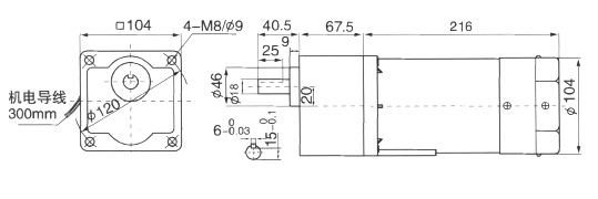 |
| Structure: Reducer+Motor+Brake | Structure: Reducer+Motor+Brake+Speed Controller (Additional) |

